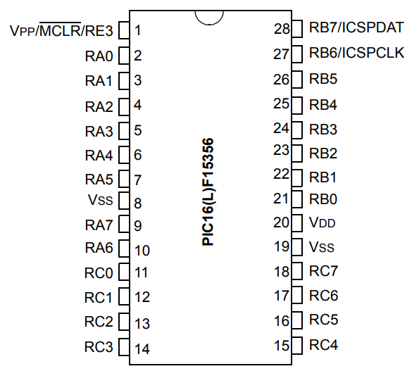
PIC Pinout
|
RA0: Speaker amplifier Enable
RA1: Station Change push button RA2: DAC output RA3: Action Select push button RA4-RA7: Message LEDs RB7 - RB0: DIP switches RC0: Transmit active LED RC1: PWM output to Servo RC2: Input Capture for reading tones RC3: General Debug pin RC4: NC RC5: NC RC6: UART-Rx RC7: UART-Tx |
Central Schematic
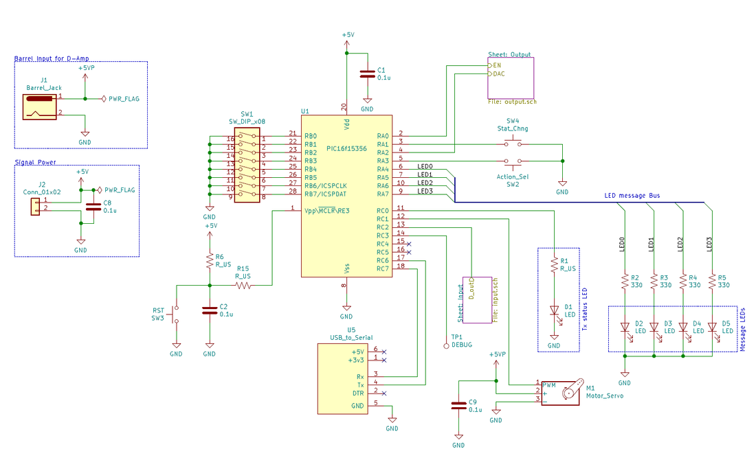
At the heart of our schematic is the PIC16F15356, an enhanced mid-range 8-bit microcontroller from Microchip. The entire system was powered from two 5V supplies, one for the servo and speaker amplifier, and another for all the digital and analog circuits. There are several items around the periphery of the microcontroller:
- Reset (SW3): General device reset
- DIP Switches: These switches are used to select the stations that the unit will operate as. RB5 selects CONN when open, RB6 selects SONAR, and RB7 selects TORPEDO. The other switches are unused.
- Station Change (SW4 ): Tells the unit to read the state of the switches and to change operation as needed
- Action Select (SW2 ): Allows the user to lock in the action they wish to do on the coming turn
- Servo: Used to press the key to transmit tones over the audio line
- USB to Serial: Converts the UART transmission to and from the PIC into USB packets to interact with a PC
- LEDs: General purpose to indicate specific events to the user. One LED lets the user know the station is transmitting
- Sheets Input and Output: For tone transmission and reception. More details in following sections.
| me218c_picing_and_screaming_sch.pdf |
Reading Tones
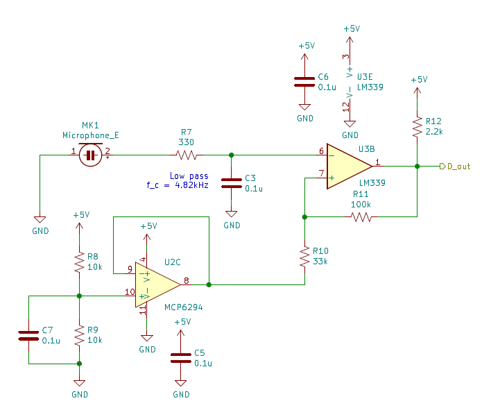
To read the tones, we opted to convert the incoming tones into a digital stream the PIC could read using input capture to determine the period of the tone. First, the output from the microphone PCBA was filtered to remove any high frequency noise and harmonics. Then, the signal is passed into a comparator circuit to produce digital pulses. Since there was a fair amount of noise in the signal, we used a comparator with relatively wide hysteresis band, 0.8V above and below 2.5V. Since the output of the microphone was biased around 2.5V, we used an op-amp (U2C) to provide a reference voltage for our comparator circuit.
Generating Tones
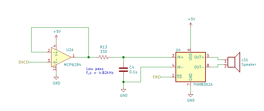
Tones are generated via the 5 bit DAC on-board the PIC. Due to the low resolution of the DAC, the signal generated has staircase that needed to be filtered out. A low pass filter was designed to remove the sharp edges and smooth out the signal. Since the DAC output excepted high impedance connected to it, we used a unity gain buffer between the DAC output pin and the low pass filter. The signal is then fed into a D-type audio amplifier PCBA which drove a small discrete speaker.
